
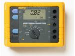
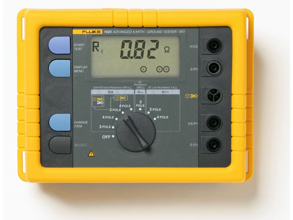
Fluke 1625-2 GEO Earth Ground Tester
- Penguji arde unik yang melakukan pengujian dengan dan tanpa pasak
- Menguji resistivitas tanah 3 dan 4 kutub, dan resistivitas tanah 4 kutub (dengan pancang)
- Melakukan pengujian batang arde pembumian selektif (satu klem + pasak)
- Melakukan pengujian batang arde tanpa pancang (dua klem)
- Fitur Automatic Frequency Control (AFC) untuk meminimalkan efek interferensi
Fluke 1625-2 GEO Earth Ground Tester adalah instrumen khusus yang digunakan untuk mengukur dan menguji sistem grounding listrik bangunan dan struktur lainnya. Ini dirancang untuk memberikan pengukuran resistansi tanah, resistivitas tanah, dan parameter terkait lainnya yang akurat dan andal.
Fluke 1625-2 Earth Ground Tester menawarkan pengujian arde yang cepat dan akurat menggunakan keempat metode pengujian.
Penguji arde Fluke 1625-2 mengukur resistansi loop arde hanya menggunakan klem, pasak saja, atau satu klem dan pasak. Dengan metode pengujian tanpa pasak, Fluke 1625-2 mampu mengukur resistansi ground loop bumi untuk sistem multi-ground dengan hanya menggunakan klem arus. Teknik ini meniadakan pekerjaan yang berbahaya dan memakan waktu untuk memutuskan arde paralel, dan menemukan lokasi yang sesuai untuk tiang arde tambahan. Hal ini memungkinkan Anda melakukan uji pentanahan di tempat yang belum pernah Anda pertimbangkan sebelumnya, seperti di dalam gedung, di tiang listrik, atau di mana pun Anda tidak memiliki akses ke tanah.
Tetap buka opsi Anda
Jika sistem pentanahan tanah berikat tidak ada untuk bangunan atau struktur yang diuji, dan hanya ada satu jalur ke tanah, Anda dapat menggunakan 1625-2 untuk melakukan metode uji potensi jatuh dengan pasak.
1625-2 menawarkan fitur canggih lainnya termasuk
Kontrol Frekuensi Otomatis untuk mengidentifikasi interferensi yang ada dan memilih frekuensi pengukuran untuk meminimalkan efeknya, sehingga memberikan nilai pembumian yang lebih akurat.
Pengukuran R* yang menghitung impedansi arde pembumian pada 55 Hz untuk mencerminkan resistansi arde pembumian yang lebih akurat yang akan terlihat oleh arde gangguan ke arde.
1625-2 juga sangat mudah digunakan. Pengaturan kecepatan aksesori kelas dunia dan waktu pengujian. Dan penguji memberi tahu Anda pasak atau klem mana yang harus disambungkan untuk setiap pengujian. Sakelar dan tombol putar yang besar mudah dioperasikan bahkan dengan tangan yang bersarung tangan. Dan Anda dapat menyimpan hingga 1500 catatan dan mengaksesnya dengan mudah melalui port USB.
Kemampuan berguna lainnya
Memberikan pengukuran R* yang menghitung impedansi pembumian bumi pada 55 Hz untuk mencerminkan resistansi pembumian yang lebih akurat yang akan terlihat oleh gangguan pembumian ke pembumian
Termasuk port USB untuk penyimpanan dan transfer data
Menampilkan peringkat IP56 untuk penggunaan di luar ruangan
Menawarkan batas yang dapat disesuaikan untuk pengujian yang lebih cepat
Dilengkapi dengan tas jinjing yang kokoh
Fitur Fluke 1625-2 GEO Earth Ground Tester
- Penguji arde unik yang melakukan pengujian dengan dan tanpa pasak
- Menguji resistivitas tanah 3 dan 4 kutub, dan resistivitas tanah 4 kutub (dengan pancang)
- Melakukan pengujian batang arde pembumian selektif (satu klem + pasak)
- Melakukan pengujian batang arde tanpa pancang (dua klem)
- Fitur Automatic Frequency Control (AFC) untuk meminimalkan efek interferensi
Spesifikasi: Fluke 1625-2 GEO Earth Ground Tester
| General Specifications | ||||
| Memory | Internal memory storage up to 1500 records accessible via USB port | |||
| Measuring function | Interference voltage and frequency, earthing resistance 3- and 4-pole with/without clip-on current transformer, resistance 2-pole with AC, 2- and 4-pole with DC | |||
| Display | 4 digit (2999 Digit) – 7 segment liquid crystal display, with improved visibility | |||
| Operation | Central rotary switch and function keys | |||
| Temperature Range | ||||
| Operating temperature | -10°C to 50°C (14°F to 122°F) | |||
| Storage temperature | -30°C to 60°C (-22°F to 140°F) | |||
| Temperature coefficient | ±0.1% of reading/°C < 18°C > 28°C | |||
| Type of protection | IP56 for case, IP40 for battery door according to EN60529 | |||
| Max voltage | Warning – socket “clamp” to socket E, ES, S or H | |||
| Urms = 0 V | ||||
| Sockets E, ES, S or H to each other in any combination, max. Urms = 250 V (pertains to misuse) | ||||
| Safety | Protection by double and/or reinforced insulation. Max. 50 V to earth per IEC61010-1. Pollution degree 2 | |||
| Quality standard | Developed, designed and manufactured to comply with DIN ISO 9001 | |||
| External field influence | Complies with DIN 43780 (8/76) | |||
| Auxiliary power | 6 x 1.5 V alkaline (IEC LR6 or type AA) | |||
| Battery life span | With IEC LR6/type AA: typ. 3,000 measurements (RE+RH ≤ 1 kΩ) | |||
| With IEC LR6/type AA: typ. 6,000 measurements (RE + RH > 10 kΩ) | ||||
| Dimensions (W x H x D) | 250 x 133 x 187 mm (9.75 x 5.25 x 7.35 in) | |||
| Weight | ≤ 1.1 kg (2.43 lb) without accessories 7.6 kg (16.8 lb) incl. accessories and batteries in carrying case | |||
| Case material | Polyester | |||
| Measurement of Interference Voltage DC + AC (UST) | ||||
| Measuring limits of error: method | Full wave rectification | |||
| Measuring range | 1 V to 50 V | |||
| Display range | 0.0 V to 50 V | |||
| Resolution | 0.1 V | |||
| Frequency range | DC/AC 45 Hz to 400 Hz sine | |||
| Accuracy | ±(5% of rdg + 5 digit) | |||
| Measuring sequence | Approx. 4 measurements/s | |||
| Internal resistance | Approx. 1.5 MΩ | |||
| Max. overload | Urms = 250 V | |||
| Measurement of Interference Frequency (F) | ||||
| Measuring limits of error: method | Measurement of oscillation period of the interference voltage | |||
| Measuring range | 6.0 Hz to 400 Hz | |||
| Display range | 16.0 Hz to 299.9 Hz to 999 Hz | |||
| Resolution | 0.1 Hz to 1 Hz | |||
| Range | 1 V to 50 V | |||
| Accuracy | ±(1% of rdg + 2 digit) | |||
| Earthing Resistance (RE) | ||||
| Measuring method | Current and voltage measurement with probe as IEC61557-5 | |||
| Open circuit voltage | 20/48 V, AC | |||
| Short circuit current | 250 mA AC | |||
| Measuring frequency | 94, 105, 111, 128 Hz selected manually or automatic. (AFC) 55 Hz in function R1 | |||
| Noise rejection | 120 dB (16 2/3 , 50 , 60, 400 Hz) | |||
| Max. overload | Urms = 250 V | |||
| Electrical Measurement Specifications | ||||
| Intrinsic Error or Influence Quantity | Reference Conditions or Specified Operating Range | Designation Code | Requirements or Test in Accordance with the Relevant Parts of IEC 1557 | Type of Test |
| Intrinsic error | Reference conditions | A | Part 5, 6.1 | R |
| Position | Reference position ±90° | E1 | Part 1, 4.2 | R |
| Supply voltage | At the limits stated by the manufacturer | E2 | Part 1, 4.2, 4.3 | R |
| Temperature | 0°C and 35°C | E3 | Part 1, 4.2 | T |
| Series interference voltage | See 4.2 and 4.3 | E4 | Part 5, 4.2, 4.3 | T |
| Resistance of the probes and auxiliary earth electrodes | 0 to 100 x RA but ≤ 50 kΩ | E5 | Part 5, 4.3 | T |
| System frequency | 99% to 101% of the nominal frequency | E7 | Part 5, 4.3 | T |
| System voltage | 85% to 110% of the nominal voltage | E8 | Part 5, 4.3 | T |
| Operating error | B = ±(|A| + 1,15 √E21 E22 E23 E24 E25 E26 ) | Part 5, 4.3 | R | |
| B[%] = ± B/fiducial value x 100%
A = intrinsic error |
||||
| Measuring range | 0.020 Ω to 300 kΩ | |||
| Display range | 0.001 Ω to 2.999 Ω | |||
| 3.00 Ω to 29.99 Ω | ||||
| 30.0 Ω to 299.9 Ω | ||||
| 0.300 kΩ to 2.999 kΩ | ||||
| 3.00 kΩ to 29.99 kΩ | ||||
| 30.0 kΩ to 299.9 kΩ | ||||
| Resolution | 0.001 Ω | |||
| 0.01 Ω | ||||
| 0.1 Ω | ||||
| 1 Ω | ||||
| 10 Ω | ||||
| 100 Ω | ||||
| Accuracy | ±(2% of rdg + 2 digit) | |||
| Operating error | ±(5% of rdg + 5 digit) | |||
| Measuring time | Typical 8 seconds with a fixed frequency 30 sec. max. with AFC and complete cycle of all measuring frequencies | |||
| Additional error because of probe-and auxiliary earth electrode resistance | RH(RS + 2000 Ω)/RE x 1.25 x 10⁻⁶% + 5 digits | |||
| Measuring error of RH and RS | Typ. 10% of RE + RS + RH | |||
| Max. probe resistance | ≤ 1 MΩ | |||
| Max. auxiliary earth electrode resistance | ≤ 1 MΩ | |||
| Automatic check if error is kept within the limits required by IEC61557-5. If after a measurement of probe-, auxiliary earth electrode- and earthing resistance, a measurement error of higher than 30% is assumed because of the influencing conditions, the display shows a warning symbol and a notice that RS or RH are too high. |
||||
| Automatic Switchover of Measuring Resolution in Dependence to Auxiliary Earth Electrode Resistance RH | ||||
| RH with Umeas = 48 V | < 300 Ω | |||
| < 6 Ω | ||||
| < 60 Ω | ||||
| < 600 Ω | ||||
| RH with Umeas = 20 V | < 250 Ω | |||
| < 2.5 kΩ | ||||
| < 25 kΩ | ||||
| < 250 kΩ | ||||
| Resolution | 1 mΩ | |||
| 10 mΩ | ||||
| 100 mΩ | ||||
| 1 Ω | ||||
| Selective Measurement of the Earthing Resistance (RE Clamp) | ||||
| Measuring method | Current and voltage measurement with probe as per EN61557-5 and current measurement in the individual branch with additional current transformer (patent applied for). | |||
| Open circuit voltage | 20/48 V AC | |||
| Short circuit current | 250 mA AC | |||
| Measuring frequency | 94, 105, 111, 128 Hz selected manually or automatically (AFC), 55 Hz (R1) | |||
| Noise rejection | 120 dB (162/3, 50, 60, 400 Hz) | |||
| Max. overload | Max. Urms = 250 V (measurement will not be started) | |||
| Measuring range | 0.020 Ω to 300 kΩ | |||
| Display range | 0.001 Ω to 2.999 Ω | |||
| 3.00 Ω to 29.99 Ω | ||||
| 30.0 Ω to 299.9 Ω | ||||
| 0.300 kΩ to 2.999 kΩ | ||||
| 3.00 kΩ to 29.99 kΩ | ||||
| Resolution | 0.001 Ω | |||
| 0.01 Ω | ||||
| 0.1 Ω | ||||
| 1 Ω | ||||
| 10 Ω | ||||
| Accuracy | ±(7% of rdg + 2 digit) | |||
| Operating error | ±(10% of rdg + 5 digit) | |||
| Additional error because of probe- and auxiliary earth typ. electrode resistance | RH(RS + 2000 Ω)/RETOTAL x 1.25 x 10⁻⁶% + 5 digits | |||
| Measuring error of RH and RS | Typ. of 10% of RETOTAL + RS + RH | |||
| Measuring time | Typ. 8 sec. with a fixed frequency 30 sec. max. with AFC and complete cycle of all measuring frequencies. | |||
| Minimal current in single branch to be measured | 0.5 mA | With transformer (1000:1) | ||
| 0.1 mA | With transformer (200:1) | |||
| Max. interference current through transformer | 3 A | With transformer (1000:1) | ||
| 1. With recommended current clamps/transformers. | ||||
| Resistance Measurement (R~) | ||||
| Measuring method | Current and voltage measurement | |||
| Measuring voltage | 20 V AC, square pulse | |||
| Short circuit current | > 250 mA AC | |||
| Measuring frequency | 94, 105, 111, 128 Hz selected manually or automatically (AFC) | |||
| Measuring range | 0.020 Ω to 300 kΩ | |||
| Display range | 0.001 Ω to 2.999 Ω | |||
| 3.00 Ω to 29.99 Ω | ||||
| 30.0 Ω to 299.9 Ω | ||||
| 300 Ω to 2999 Ω | ||||
| 3.00 kΩ to 29.99 kΩ | ||||
| 30.0 kΩ to 299.9 kΩ | ||||
| Resolution | 0.001 Ω | |||
| 0.01 Ω | ||||
| 0.1 Ω | ||||
| 1 Ω | ||||
| 10 Ω | ||||
| 100 Ω | ||||
| Accuracy | ±(2% of rdg + 2 digit) | |||
| Operating error | ±(5% of rdg + 5 digit) | |||
| Measuring time | Typical 6 seconds | |||
| Max. interference voltage | 24 V, with higher voltages measurement will not be started | |||
| Max overload | Urms max. = 250 V | |||
| Resistance Measurement (R DC) | ||||
| Measuring method | Current- voltage measurement as per IEC61557-4 possible | |||
| Measuring voltage | 20 V DC | |||
| Short circuit current | 250 mA DC | |||
| Formation of measured value | With 4-pole measurement wires on H, S, ES can be extended without additional error. Resistances > 1 Ω in wire E can cause additional error of 5m Ω/Ω. |
|||
| Measuring range | 0.020 Ω to 300 kΩ | |||
| Display range | 0.001 Ω to 2.999 Ω | |||
| 3.00 Ω to 29.99 Ω | ||||
| 30.0 Ω to 299.9 Ω | ||||
| 300 Ω to 2999 Ω | ||||
| 3.0 kΩ to 29.99 kΩ | ||||
| 30.0 kΩ to 299.9 kΩ | ||||
| Resolution | 0.001 Ω | |||
| 0.01 Ω | ||||
| 0.1 Ω | ||||
| 1 Ω | ||||
| 10 Ω | ||||
| 100 Ω | ||||
| Accuracy | ±(2% of rdg + 2 digit) | |||
| Operating error | ±(5% of rdg + 5 digit) | |||
| Measuring sequence | Approx. 2 measurements/s | |||
| Measuring time | Typical 4 second including reversal of polarity (2-pole or 4-pole) | |||
| Maximum interference voltage | ≤ 3 V AC or DC, with higher voltages measurement will not be started | |||
| Maximum inductivity | 2 Henry | |||
| Maximum overload | Urms = 250 V | |||
| Compensation of Lead Resistance (RK) | ||||
| Compensation of lead resistance (RK) can be switched on in functions RE 3-pole, RE 4-pole (clamp), R AC, and R DC 2-pole | ||||
| Formation of measured value | Rdisplay = Rmeasured – Rcompensated2 | |||
| 2. Value of setpoint entry RK = 0.000 Ω, variable from 0.000 to 29.99 Ω by means of measuring adjustment. | ||||
| Stakeless Ground Loop Measurement (Two Clamp Stakeless) | ||||
| Switch position | RA 4-pole (two clamp Stakeless) | |||
| Resolution | 0.001 Ω to 0.1 Ω | |||
| Measuring range | 0.02 Ω to 199.9 Ω | |||
| Accuracy | ±(7% rdg + 3 digit) | |||
| Operating error | ±(10% rdg + 5 digit) | |||
| Measuring voltage | Vm = 48 V AC (primary) | |||
| Measuring frequency | 128 Hz | |||
| Noise current (IEXT) | Max. IEXT = 10 A (AC) (RA < 20 Ω) | |||
| Max. IEXT = 2 A (AC) (RA > 20 Ω) | ||||
| Measuring principle: Stakeless measurement of resistance in closed loops using two current transformers. Automatic range selection. The information regarding stakeless ground loop measurements is only valid when used in conjunction with the recommended current clamps at the minimum distance specified. |
||||
Q & A
Related Products
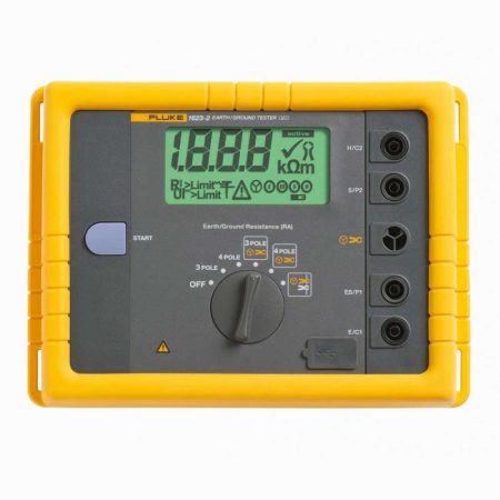
- Penguji arde unik yang melakukan pengujian cepat dan akurat dengan dan tanpa pasak
- Menguji resistivitas tanah 3 dan 4 kutub, dan resistivitas tanah 4 kutub (dengan pancang)
- Melakukan pengujian batang arde pembumian selektif (satu klem + pasak)
- Melakukan pengujian batang arde tanpa pancang (dua klem)
- Menampilkan peringkat IP56 untuk penggunaan di luar ruangan
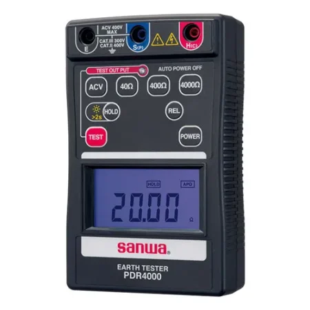
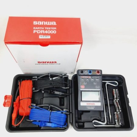
Sanwa PDR4000 Digital Earth Tester cocok untuk pekerjaan kelistrikan, grounding sistem proteksi, dan pengukuran keamanan instalasi listrik.
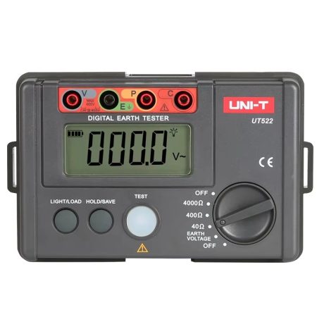
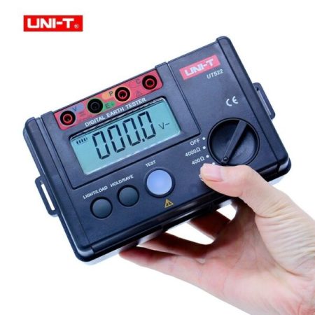
NI-T UT522 Digital Earth Testers dapat melakukan pengukuran resistansi bumi 3-kawat dan 2-kawat yang tepat dan sederhana untuk sistem daya dan listrik, peralatan proteksi petir, dan sistem pentanahan semua peralatan listrik. Seri ini merupakan penguji resistansi bumi pertama UNI-T dengan nilai ekonomis yang tinggi. Desainnya yang ringan memudahkan pekerjaan lapangan.
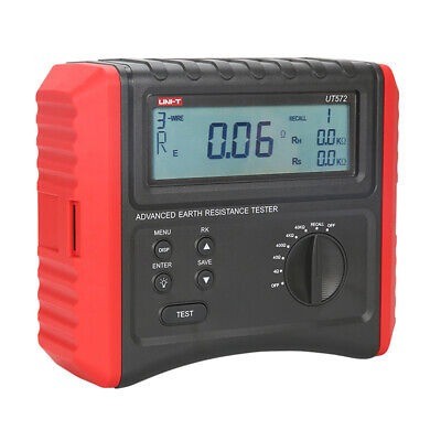
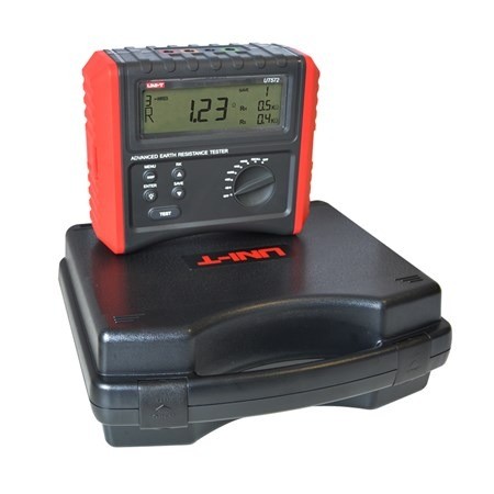
UT572 digunakan untuk mengukur resistansi bumi dan resistivitas tanah. Alat ini dapat secara otomatis memeriksa koneksi antarmuka dan mendeteksi tegangan/frekuensi interferensi, dengan fungsi penyimpanan data dan indikasi. Alat ini dapat melakukan pengukuran 2/3/4-kawat untuk berbagai aplikasi di lokasi, seperti kabel peralatan listrik dan peralatan proteksi petir.
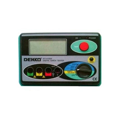
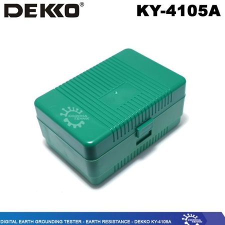
Dekko KY-4105A adalah alat yang biasa digunakan untuk pengukuran tegangan bumi yang biasa dipakai oleh surveyor PLN, Telkom, atau Kontraktor untuk konstruksi pembangunan.
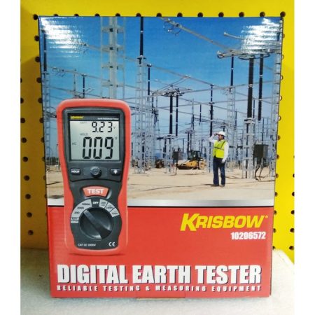
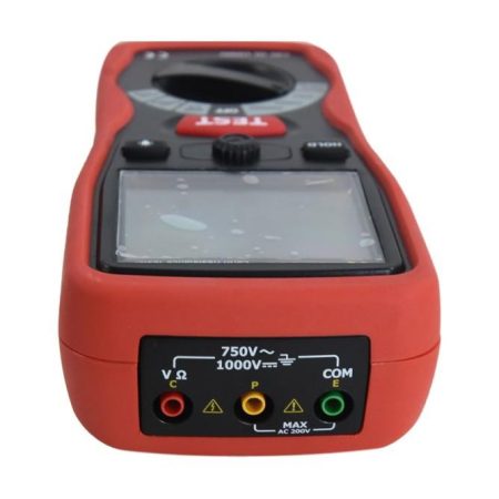
Krisbow Earth Tester Digital 2000 ohm adalah alat yang digunakan untuk mengukur resistansi tanah dan kinerja sistem grounding. Alat ini dapat membantu menentukan apakah grounding yang ada memenuhi standar yang diperlukan untuk sistem listrik dan elektronik.
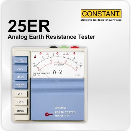
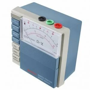
Constant 25ER Analog Earth Resistance Tester adalah suatu alat ukur yang digunakan untuk mengukur tahanan pentanahan baik untuk mengukur tahanan pentanahan instalasi penangkal petir maupun mengukur tahanan pentanahan untuk instalasi listrik.
- Beroperasi Dengan Pengaruh Minimum Dari Tegangan Bumi Dan Tahanan Bumi Dari Batang Bumi Tambahan
- Metode Pengukuran Tahanan Bumi yang Disederhanakan
- Fasilitas Pemeriksaan Mandiri Untuk Memeriksa Baterai Dan Koneksi Kawat Timbal
- Tekan Tombol Sakelar Untuk Pengoperasian Instrumen yang Lancar
- Menahan Tegangan (1500VAC) Selama Satu Menit Antara Sirkuit Listrik Dan Casing Perumahan
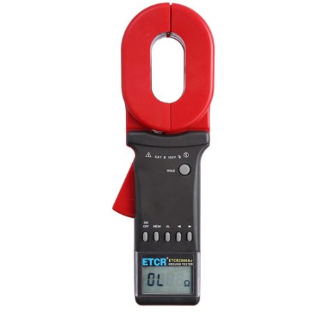
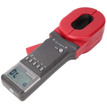
Clamp Resistance Tester berkualitas dari ETCR Electronics Dengan ukuran penjepit 65mm X 32mm.
- Pengukuran resistansi bumi, resistansi loop
- Rentang Ukur: 0,010Ω~200Ω
- Penyimpanan Data: 99 set
- Pengaturan Ambang Alarm: 1-199Ω
- Fungsi Alarm: alarm terdengar dan terlihat
- Ukuran CT: 65mmX32mm
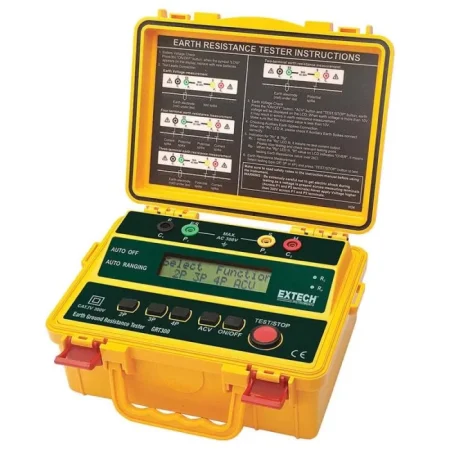
Dengan desain portable dan dilengkapi aksesori pengujian lengkap, Extech GRT300 banyak digunakan untuk inspeksi instalasi listrik, sistem proteksi petir, industri, dan maintenance fasilitas.
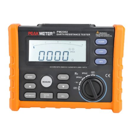
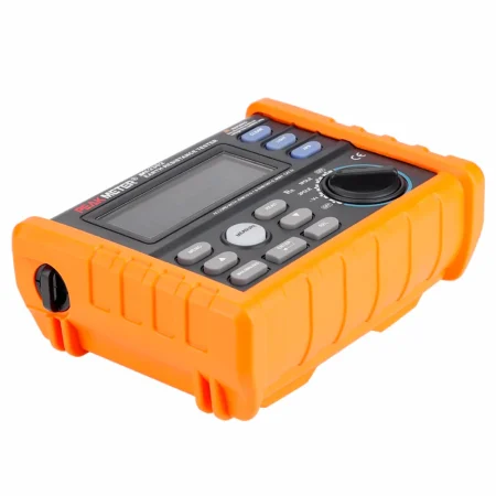
Penting untuk diperhatikan bahwa spesifikasi dan fitur perangkat elektronik seperti Peakmeter PM2302/MS2302 Earth Resistance Tester dapat bervariasi dari waktu ke waktu, karena produsen dapat memperbarui atau merilis versi baru dari produk mereka. Untuk informasi yang paling akurat dan terkini tentang model khusus ini, saya sarankan merujuk ke dokumentasi resmi yang disediakan oleh pabrikan atau menghubungi dukungan pelanggan mereka.
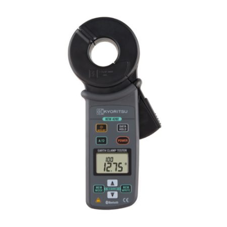
Beberapa model dilengkapi komunikasi Bluetooth yang memungkinkan data pengukuran ditransfer dan direkam ke perangkat Android untuk analisis lebih lanjut.
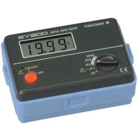
- Dirancang dengan standar keselamatan IEC 61557
- Referensi ke IEC 60529: Tingkat perlindungan yang diberikan oleh selungkup (IP54). Pengukuran dapat dilakukan bahkan dalam kondisi cuaca buruk
- Layar digital LCD besar dan mudah dibaca
- Kabel uji 2P (untuk pengukuran yang disederhanakan) memiliki struktur yang dilengkapi dengan klip buaya pengaman dan probe uji
- Memperingatkan ketika resistansi bumi dari lonjakan bumi tambahan melebihi batas yang diizinkan
- Tas lembut yang nyaman untuk dibawa untuk aksesori dll.
Reviews
There are no reviews yet.